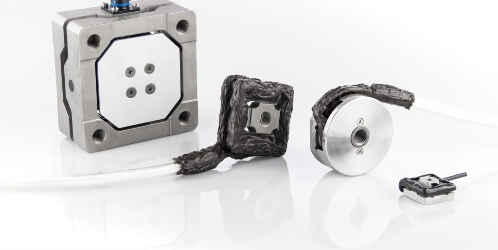
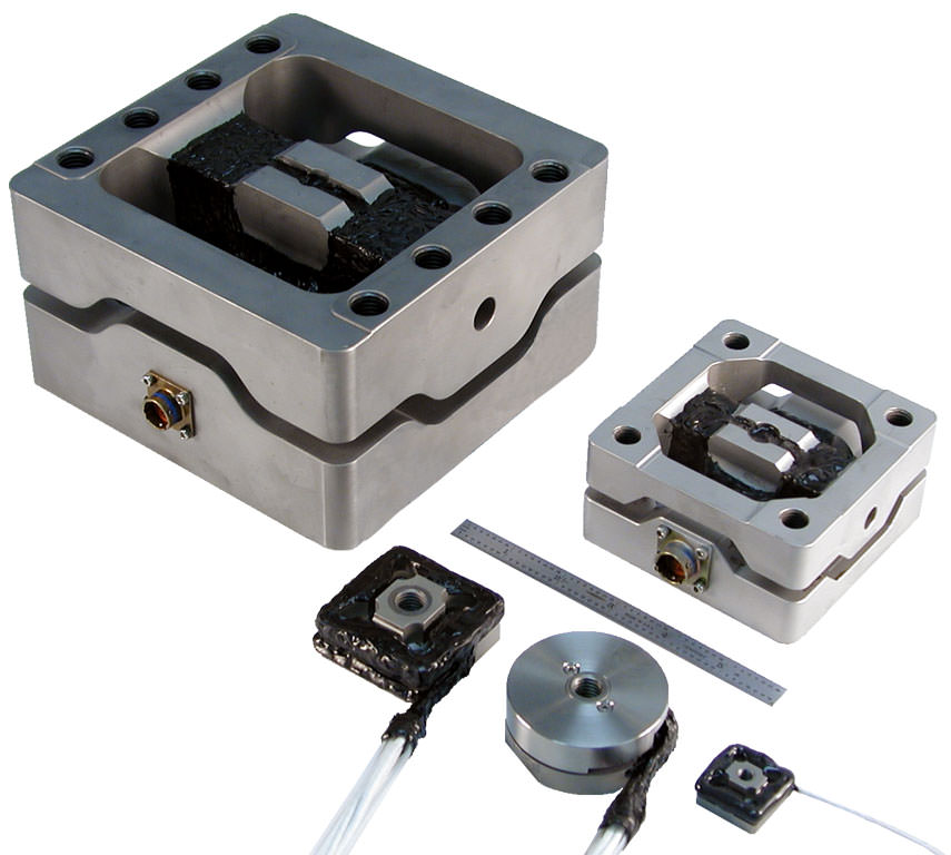
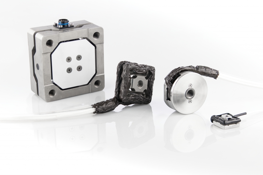
The TR3D family of Three Axis Load Cells provide a solution to a variety of force measurement needs. Standard models provide load capacities from 250 lb. to 100,000 lb. in three orthogonal directions. These load cells are used in a vast array of applications including motorcycle axle and suspension force measurements, force measurements at the vehicle tire patch, force sensors for feedback control of test stands, and many more. By using an array of the three axis load cells, it is also possible to measure moment loads. For more load measuring equipment, see our other transducers.
Features
- Measures forces in three perpendicular directions
- Environmentally protected
- Individually calibrated and temperature compensated to ensure maximum accuracy
- Rugged construction
- Any model can be provided as a one-directional unit
- The Quality Management System is accredited to the ISO 9001:2015 and ISO 17025:2017 standards
Overview
Load Cell Design and Manufacture
Each load cell transducer is machined from a solid block of stainless steel or aluminum, which helps ensure that the load cell maintains excellent linearity throughout the entire force range, both positive and negative. Hysteresis is virtually nonexistent.
Crosstalk (the sensitivity of a given channel to loading of other measurement channels or extraneous loading) is minimized by careful arrangement of individual load paths and strain gage elements. As a result, loads applied to other axes and other extraneous loading have no effect on the signal outputs of each axis.
Weatherproof coatings are applied to all strain-gaged surfaces, which guarantees that the load cells survive in any environment experienced in industrial or automotive applications.
What Makes Michigan Scientific Corporation’s TR3D Load Cells Unique?
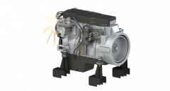
Michigan Scientific Three Directional Load Cell transducers offer a superior solution over traditional one-directional load cells because they provide more information in a compact package. Often, Three Directional Load Cells are used in applications where an array of one-direction load cells are simply too big and bulky. One such application is replacing engine mounts with Three Directional Load Cells. This allows the measurement of the vector force reacted by the frame without changing how the engine and vehicle attach.
Measuring Forces and Moments
When two or more Three Directional Load Cells are used in a fixturing arrangement, the user can take advantage of the known geometry that is separating the load cells in order to calculate the applied moments as well as forces to which a body is subjected. Thus, it is possible to quantify the loading on all six degrees of freedom of the object under test.
Aircraft Loading Ramp Application
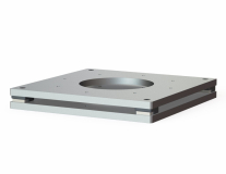
One successful application example of this concept is an aircraft loading ramp that Michigan Scientific instrumented for the military. Designers of the ramp were able to quantify the loads placed on the ramp as vehicles are loaded. To do this, four Three Directional Load Cells were sandwiched between two plates. A series of these plates were then inserted into a loading ramp and vehicles were driven over them. This allowed for a complete description of the loading condition placed on the ramp by the vehicle as it moved.
Michigan Scientific Three Directional Load Cells are configured for easy mounting in a variety of applications using standard hardware. If access is limited, most models are mounted entirely from one side through the use of a bottom thread adapter.
In many applications, the use of a stand-alone force measuring device may not be the most practical solution. In these cases, Michigan Scientific Corporation works closely with the customer to develop a custom measurement device. This is done by either instrumenting production parts, or by replacing production parts with a custom transducer. If you have an application where production Load Cells are not an ideal option, please contact us about a custom solution.
Calibration
We have spent years perfecting our unique, patented transducer calibration machine, the TCAT. A calibration compares the electrical output of a transducer to the applied loads. The TCAT can calibrate all MSC multi-axis load cells, Wheel Force Transducers, and Wheel Torque Transducers. The TCAT applies loads with linear actuators and measures the load through the transducer via reaction links. It applies three forces and three moments and calibrates through each transducer’s unique electronics package. In addition to the TCAT, MSC has a large calibration that uses hydraulic arms to apply forces and moments; up to 100,000 lbs.
The Michigan Scientific transducer calibration process complies with ISO9001:2015 and ISO17025:2017 requirements and all reference measurement equipment is traceable to National Institute of Standards and Technology (NIST). It is recommended that customers send in their transducers after one year of use, and then every two years after that. This is an easy way to ensure that the transducer is functioning properly and has not incurred any damage during use.
With the development of the patented transducer calibration machine, calibration time has significantly decreased, allowing for a faster turnaround and return to customer. There are multiple locations throughout the globe to get a Michigan Scientific transducer calibrated. The calibration process is now also automated, which allows our highly skilled technicians to focus on transducer design and manufacturing improvements.
Documents
Applications
Related Products
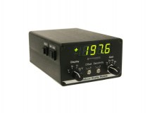
Gain and shunt selected based on load cell being used
Available with any number of channels
Related Blog Posts
Models
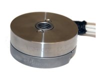
1,000 lb, 3,000 lb, 5,000 lb, and 10,000 lb capacities
Measures forces in 3 perpendicular directions
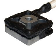
250 lb to 16,000 lb capacities
Measures forces in 3 perpendicular directions
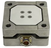
10,000 lb, 16,000 lb, and 40,000 lb capacities
Measures forces in 3 perpendicular directions
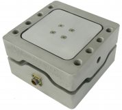
100,000 lb capacity
Measures forces in 3 perpendicular directions


Last Modified:
