
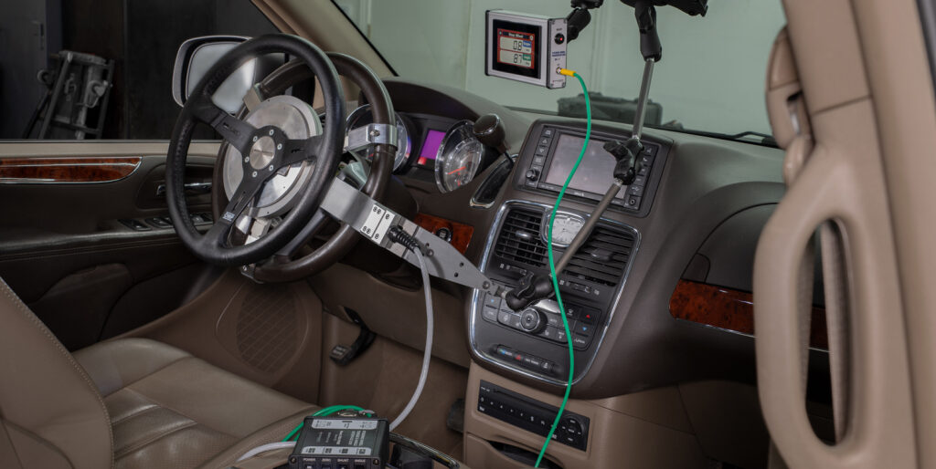
Accurately measuring driver input is critical to understanding vehicle performance, driver behavior, and occupant response. Forces applied by the driver, and forces experienced by the driver, directly influence brake development, steering tuning, ride and handling, and ADAS validation.
Michigan Scientific supports driver‑focused testing by measuring forces at the human–vehicle interface. The examples below highlight several ways these measurements are captured using standard and custom Michigan Scientific instrumentation equipment.
Steering Wheel Torque and Angle Measurement
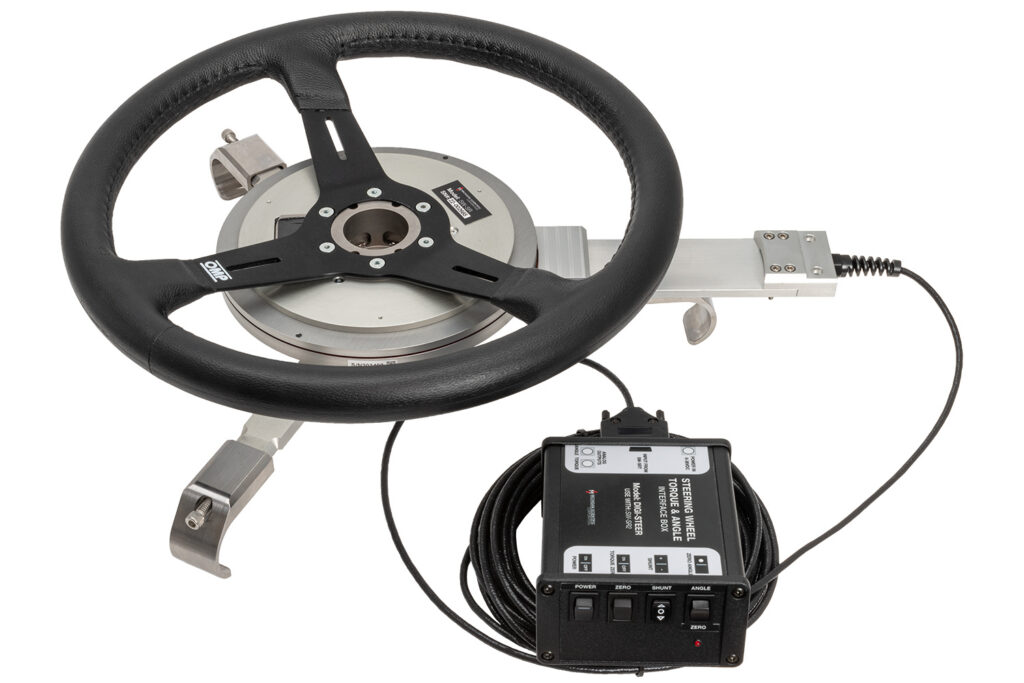
Steering wheel torque and angle measurement quantifies driver steering effort and control. These signals are critical for steering system development, electric power steering calibration, and ADAS evaluation.
The SW‑SR2 Steering Wheel Torque and Angle Transducer measures:
- Steering torque applied by the driver
- Steering wheel angle
This data helps engineers evaluate steering feel, driver workload, and steering system response under real‑world conditions.
Brake Pedal Force Measurement
Brake pedal force measurement captures driver braking intent directly at the pedal. This data is essential for correlating braking effort with deceleration, brake system response, and vehicle stability.
Michigan Scientific’s Brake Pedal Force Transducers (BPFT series) mount directly to production pedals while maintaining realistic pedal feel. These sensors are commonly used for:
- Brake system development
- Brake balance and tuning
- Driver behavior and repeatability studies
Brake pedal force data is often synchronized with vehicle speed, wheel force, and longitudinal acceleration measurements.
Custom Shift and Control Effort Measurement
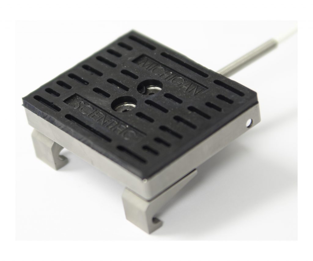
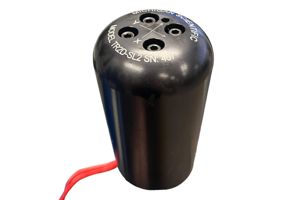
Many test programs require measurement of driver controls, such as shift knobs, levers, hand controls, or other operator interfaces. Michigan Scientific designs custom strain-gage-based transducers to measure shift effort and control forces while preserving ergonomics and normal operation. These measurements support:
Michigan Scientific designs custom strain‑gage‑based transducers to measure shift effort and control forces while preserving ergonomics and normal operation. These measurements support:
- Shift effort and consistency analysis
- Control usability and ergonomics evaluation
- Driver workload assessment
- Development and validation of adaptive or accessibility-focused vehicle controls
Custom solutions allow instrumentation to be tailored to the vehicle, control geometry, and test objectives, including specialized interfaces designed for drivers with limited mobility or alternative input methods.
Seat Belt Load Measurement
Seat belt load measurement captures restraint forces acting on the occupant during braking, cornering, and dynamic maneuvers.
Seat belt transducers provide insight into:
- Load transfer during aggressive events
- Occupant interaction with restraint systems
This data complements pedal and steering input measurements by showing how driver actions translate into physical loads on the occupant.
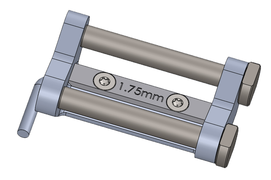
Measuring Driver–Seat Interaction Using Multi‑Axis Load Cells
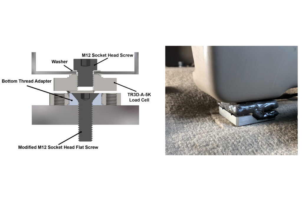
Driver response to vehicle motion can also be measured at the seat interface. TR3D Multi‑Axis Load Cells can be integrated into seat structures to measure forces transmitted between the driver and the seat.
Seat force measurements support analysis of:
- Occupant load distribution
- Driver reaction to braking, acceleration, and cornering
- Ride comfort and seating ergonomics
When combined with steering, pedal, and restraint measurements, seat force data helps close the loop between driver input and occupant response.
A System‑Level View of Driver Interaction
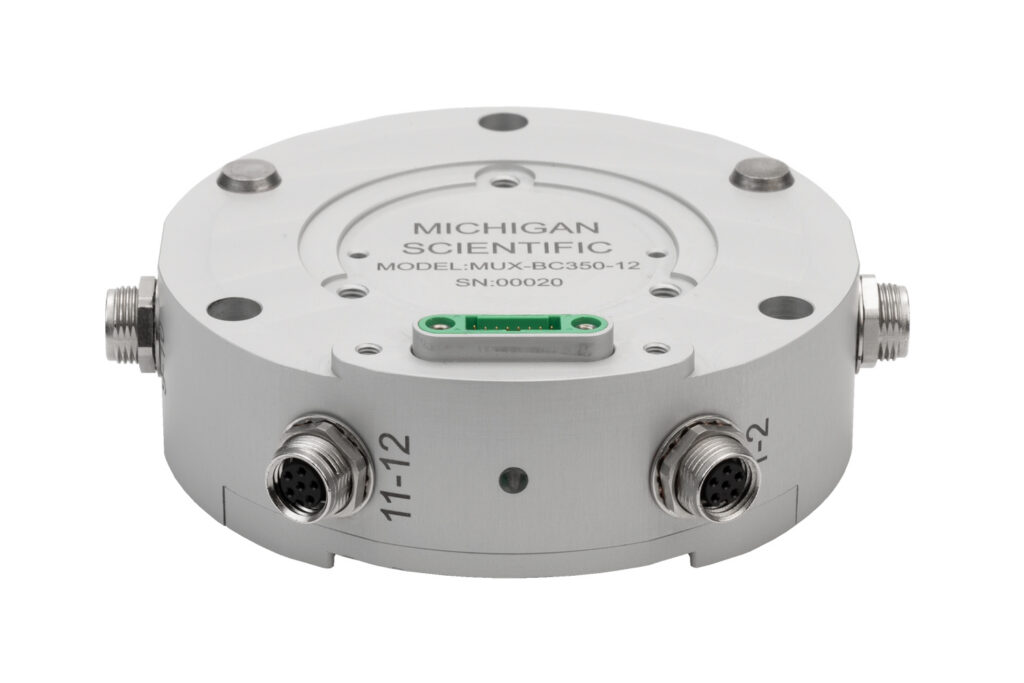
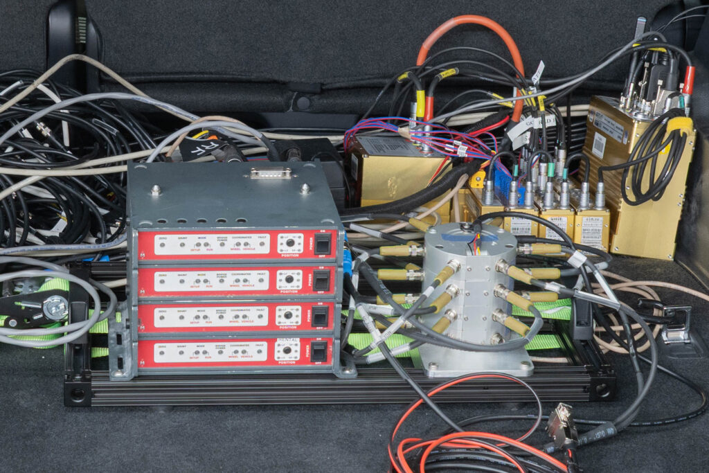
Multiple driver input and occupant interaction measurements can be synchronized using Michigan Scientific’s 12-Channel Analog to CAN Module. The MUX signal conditioning and CAN‑based data acquisition solutions. The MUX delivers clean, digital, time‑aligned output from twelve channels over a single CAN 2.0 or CAN FD bus. Up to 4 modules can be stacked, enabling synchronized sampling of up to 48 channels.
By stacking different MUX models within one mechanically unified assembly, the platform supports mixed‑sensor configurations—strain, temperature, displacement, acceleration, RTD, and encoder inputs—all consolidated onto a single CAN output.
Michigan Scientific’s 12-Channel Analog to CAN Modules bring modern, digital, synchronized signal conditioning into a compact package designed for today’s demanding test environments. Whether you’re instrumenting a rotating shaft, outfitting a full vehicle, or building a multi-sensor thermal map, the MUX provides the speed, accuracy, and reliability to collect clean, actionable data.
By measuring forces at the driver interface, engineers gain a more complete understanding of how human input influences vehicle behavior and how the vehicle physically interacts with the driver.