Features
- Combines forces from multiple load cells
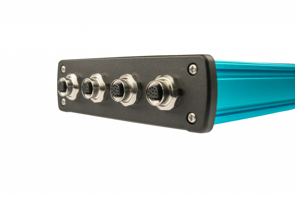
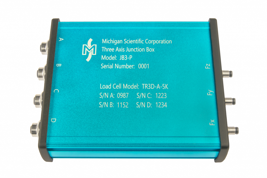
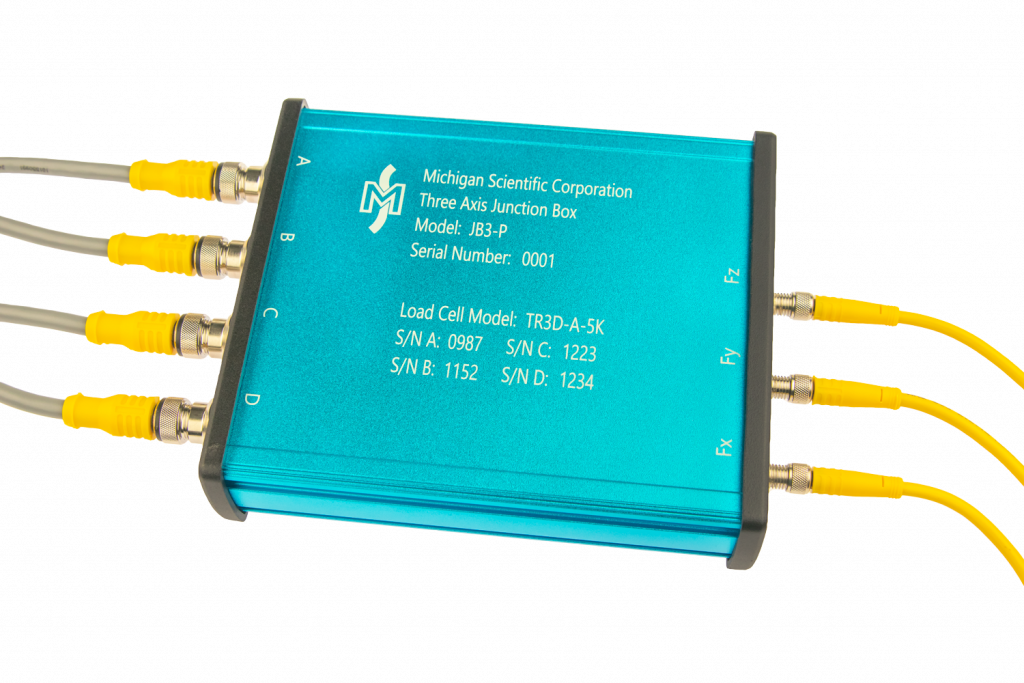
- Connect up to four Three Axis Load Cells
- Three output channels
- Amplified version available
Description
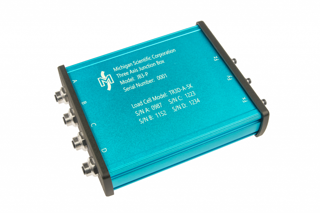
The JB3 combines the signals from multiple TR3D Load Cells and outputs the total force acting on a load cell array or load platform. Up to four three axis load cells can be connected to the JB3. The unamplified version (JB3-P) can be connected to most strain gauge bridge data acquisition modules. The amplified version (JB3-A) has a ±10 V output and can be connected to any high level voltage data recorder.
A load cell array or load platform using four three axis load cells will have 12 independent output channels. To calculate the total force acting on the array, all 12 channels have to be recorded and combined in post-processing. The JB3 combines the output from each load cell so that the user only has to record three channels. The JB3 also eliminates the need for any post-processing summing calculations. The JB3 has a sensitivity trimming circuit for each input to equalize the sensitivity of each load cell. This ensures the output will remain constant regardless of where the load is applied to the array or load platform. The load cells are connected in parallel, so the effective bridge resistance of the output channels will be one quarter of the nominal bridge resistance of the load cells. For load cell array and load platform applications, the TR3D Load Cells are built with a nominal bridge resistance of 1,000 Ω so the effective bridge resistance of the junction box output is 250 Ω.
Documents
Last Modified:


