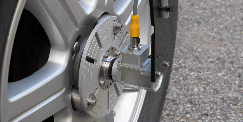
The Michigan Scientific High Resolution Wheel Pulse Transducer (WPT) is an optical encoder which attaches to the lug nuts of a vehicle’s wheel. The WPT is commonly used to track a vehicle’s position and speed for applications such as fleet management and autonomous vehicle tracking. This case study will demonstrate the accuracy of using two Wheel Pulse Transducers together, comparing the position and velocity measurements to GPS data.
How It Works
The signal from the encoder is used to calculate the angular position and velocity of the wheel. Data recorded by two WPTs on either side of the car can be averaged to find the center, thus giving the most accurate representation of the distance and speed the car has traveled. Mapping vehicles often use WPTs to compensate for breaks in GPS signal, allowing tracking of the distance traveled during the signal loss. In this study, the high resolution of the WPT data performed much better than that of the GPS sensor that was used due to its high sampling rate of 10,000 Hz.
Test Setup
To compare the Wheel Pulse Transducer results to the GPS results, two WPT systems were attached to a vehicle, one on the rear-right side and one on the rear-left side. The transducers were assembled on the rear wheels so that the turning motion of the front wheels would not have to be compensated for in the data. A GPS device was placed on top of the vehicle, in the center of the roof above the rear wheels, where it would give the most accurate reading. Left and right WPT distances and speeds were averaged to match the GPS signal at the center of the vehicle. The mile-long course shown below, along with a latitude and longitude plot from the GPS, includes a round-about and a zigzag maneuver.
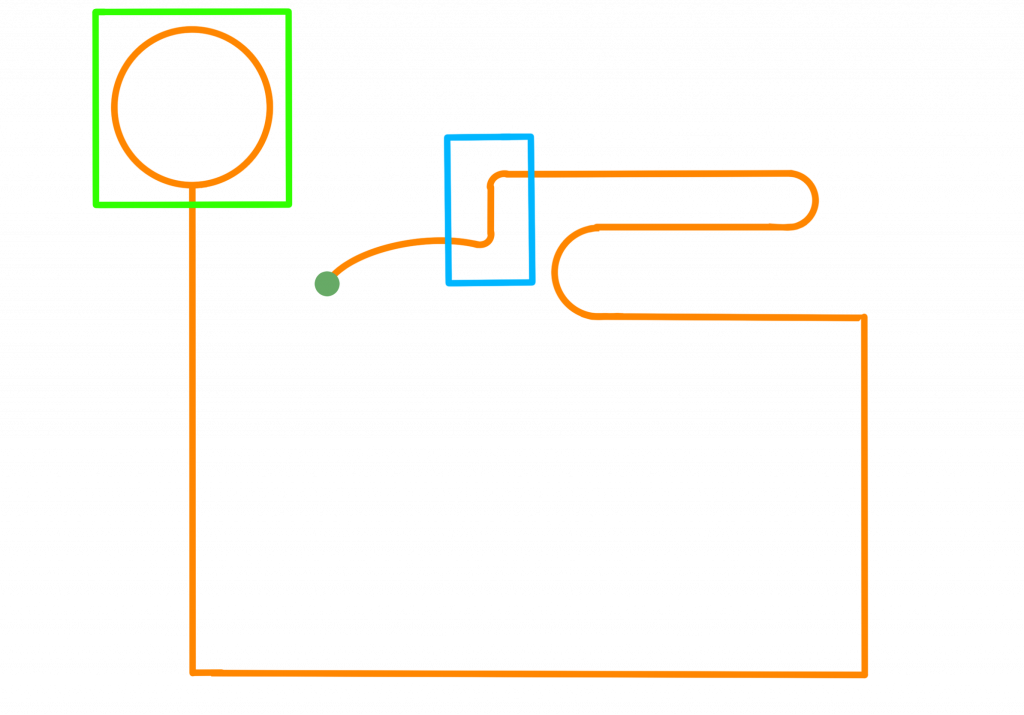
Test Track Outline
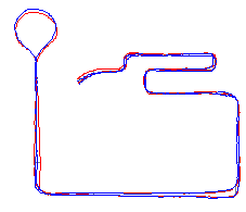
GPS Data from Test Track
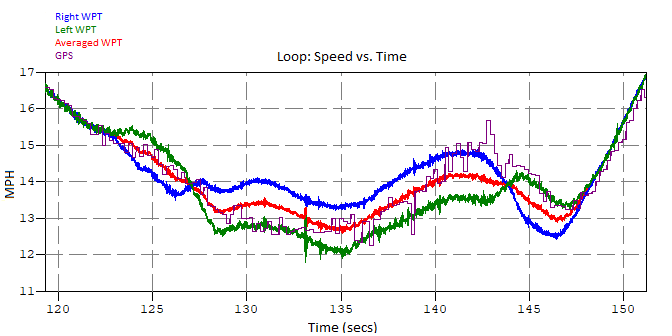
Loop
When going counterclockwise around the circular part of the test track (shown in green above), one would expect the velocity and distance of the right wheel to measure much higher than the left. Looking at the data, shown below, this is found to be true. The right (blue) and left (green) wheel velocities are averaged (red), and line up nearly perfectly with the GPS data (purple).
Zigzag Path
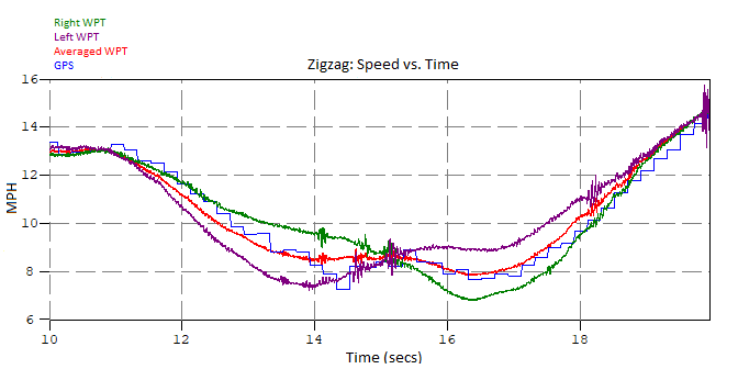
The area containing a quick right and left turn, shown within the blue square on the test track outline provides another interesting perspective. For the velocity plot below, the vehicle was maneuvered with a quick left turn, then an immediate right. The “W” shape created by this shows that the left wheel (purple) went slower than the right (green) around the left turn, then the left went faster than the right around the right turn. While the two opposing sides trade places throughout the maneuver, the calculated average (red) and the GPS data (blue) stay close together in the middle.
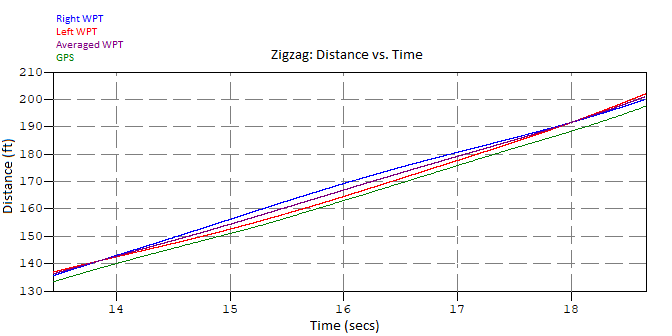
The time in between the two intersection points on the graph below is where the left and right turns occurred. The right wheel (blue) surpasses the left wheel (red) in distance traveled as it has a larger radius to go around during the left turn, which starts around 14 seconds and ends at approximately 15.5 seconds. At this point, the right wheel has traveled farther than the left wheel. The right turn begins just before 17 seconds, and the left wheel catches up with the right wheel by the time the turn ends at approximately 18 seconds. The average (purple) distance traveled stays centered between the two. Because the slope of the average distance and the GPS is the same, they are still recording the same speed and change in distance. However, the GPS is lagging a few feet behind the wheel, hence the slight offset in the data.
Error
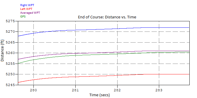
The last few data points of the test can show the benefits of using two WPTs rather than just one. If only one WPT was used, the recorded distances would have a maximum error of 0.22%. However, by installing two WPTs and averaging them, the error is only 0.0115%, a decrease of a factor of 19. This shows that using two Wheel Pulse Transducers can help to reduce error that can accumulate over multiple turns.
This test is just one of a multitude of different tests that utilize Wheel Pulse Transducers. Having a durable and precise measurement system is beneficial for accurately tracking a vehicle’s position and speed in any environment. If you would like to discuss your wheel testing application, contact a Michigan Scientific representative today.