The PVSR
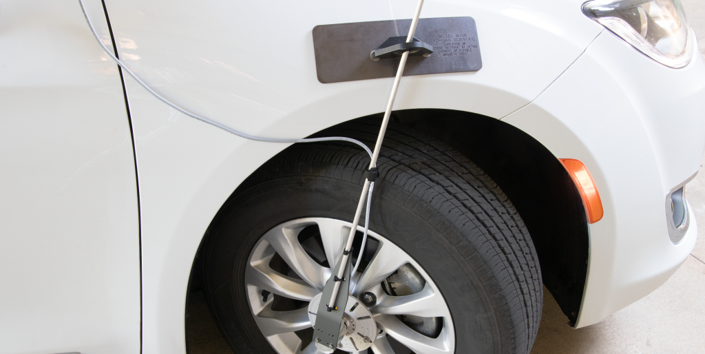
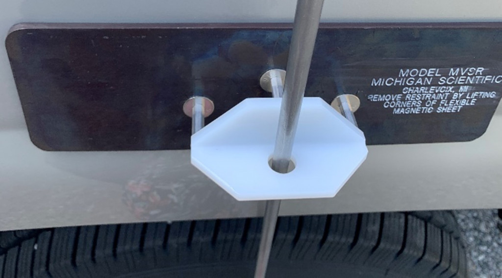
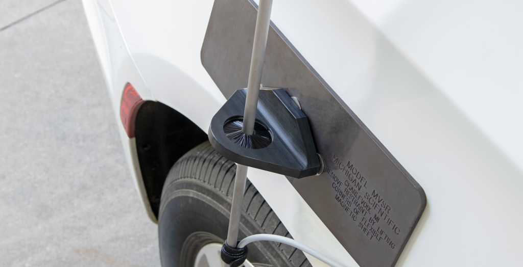
Michigan Scientific’s Precision Vehicle Stator Restraint (PVSR) is designed to attach to any vehicle body, no matter how big or curved the surface is. The PVSR is used to prevent the stationary part, the stator, of measurement devices from rotating while the vehicle wheel is rotating. The PVSR is constructed of a flexible magnetic sheet, which attaches to the vehicle body, and a protruding holder for the stator restraining rod. The restraining rod attaches to the stator of Wheel Pulse Transducers (WPT), as well as slip ring components within the Wheel Force Transducer and Wheel Torque Transducer assemblies. The PVSR is a variation of Michigan Scientific’s Magnetic Vehicle Stator Restraint (MVSR) that now includes a disk brush insert. It is designed to keep the restraint rod centered within holder. The PVSR is preferred when measuring wheel rotation at near-zero speeds, or during tests where wheel rotation may change direction between forward and reverse.
Testing
It is important to understand the benefits of using the PVSR. This case study will be used to demonstrate how the PVSR can help to reduce error in vehicle distance and velocity measurements at low speeds. Testing was conducted using a WPT and four different tests; stop and go, rollback, hard stop, and the “wiggle” test. The full WPT assembly was attached to the rear left wheel on a vehicle with the restraining rod using the PVSR, shown below on the left. These tests were then repeated using the Original MVSR without the disk brush inside, shown below on the right. Video was used to compare graphical angular motion data to visual results.
Results
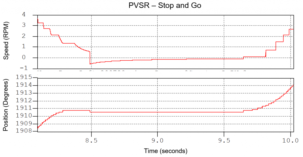
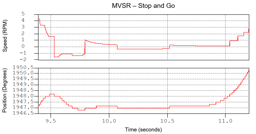
Stop and Go
This test consisted of rolling the vehicle up to a mark, coming to a complete stop, then releasing the brake and rolling forward.
PVSR
There was no oscillation of the restraining rod or wheel detected by the WPT or video, as shown by the straight lines in both the velocity and position data above.
Original MVSR
There was a slight oscillation upon stopping and a pulse backward when the brake is released. This is due to oscillation of the restraint rod in the Original MVSR.
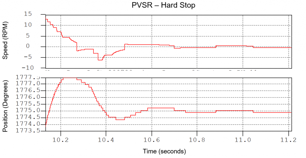
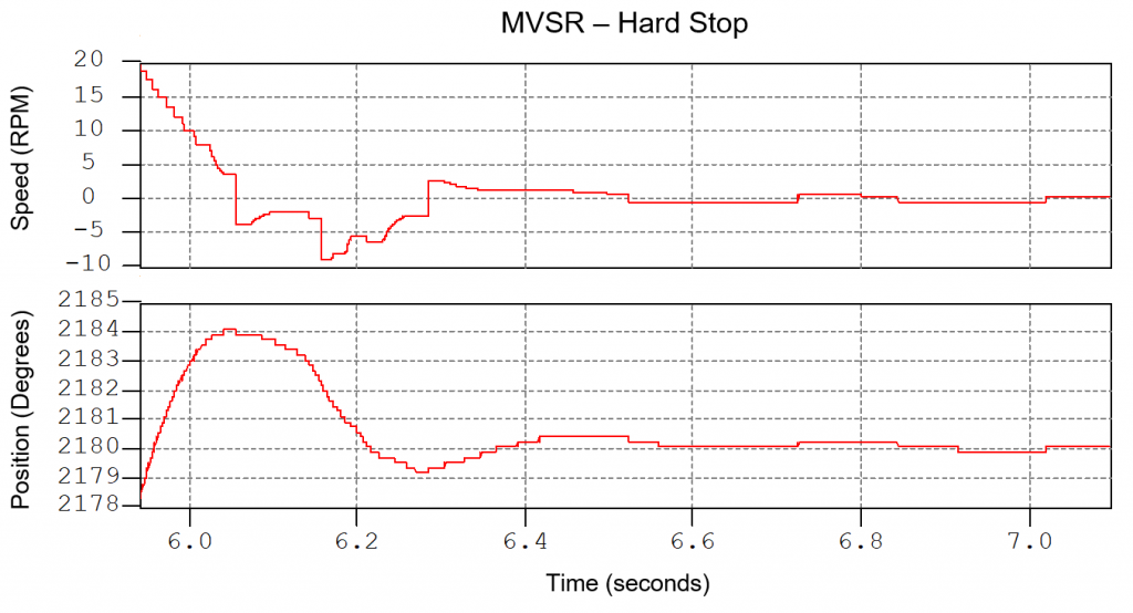
Hard Stop
This test involved accelerating up to a mark then braking hard to come to a complete stop.
PVSR
There was a slight oscillation of the restraining rod due to the wheel oscillating upon stopping.
Original MVSR
Similar to the PVSR, there was an oscillation upon stopping. This is seen in both the data and the video. However, this data shows a significantly larger oscillation in the Original MVSR than the PVSR.
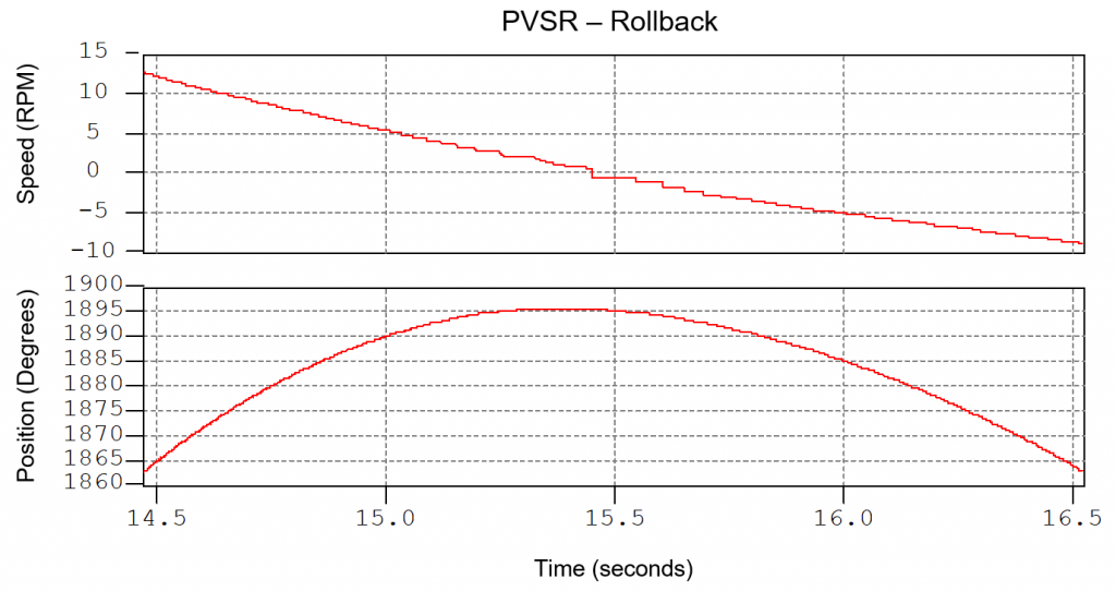
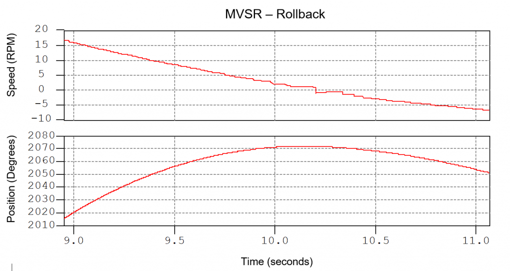
Rollback
The rollback test started with the vehicle positioned on a ramp where it accelerated slightly, slows to a stop, then rolls backward.
PVSR
There was no oscillation, meaning the restraining rod stayed centered within the PVSR.
Original MVSR
There was no apparent oscillation of the restraining rod in the Original MVSR.
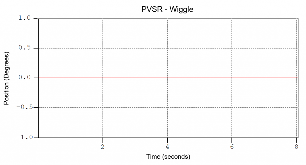
“Wiggle”
The test with the most dramatic results was also the simplest. With a hand, the restraining rod was moved back and forth in the PVSR and MVSR.
PVSR
The disk brush had no displacement and no noise when moved. This was expected as the disk brush was implemented with the intention to correct this type of behavior.
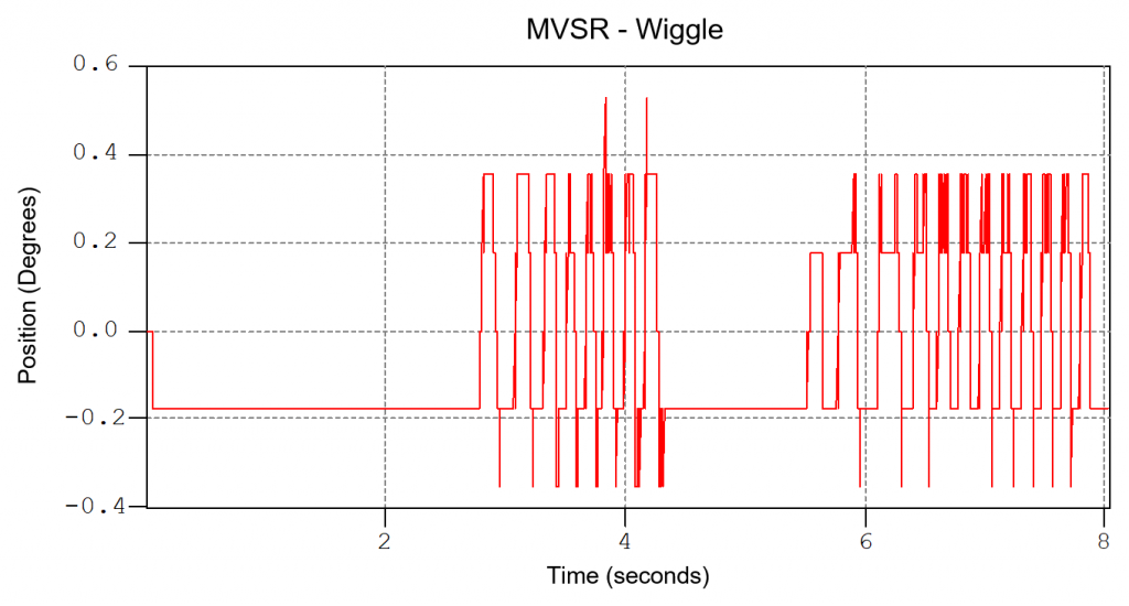
Original MVSR
Large amounts of was introduced into the system as there was nothing to hold the rod in place within the circular area in the MVSR. This noise could occur on uneven terrain when this type of MVSR is used.
This case study demonstrates a situation in which a PVSR may be preferred to the original MVSR. Using measurement equipment that works to minimize error is beneficial for accurately collecting data in any environment. If you would like to discuss your testing application, contact a Michigan Scientific representative today.